Anisotropic terahertz microspectroscopy (ATM) is a spectroscopic technique in which molecular vibrations in an anisotropic material are probed with short pulses of terahertz radiation whose electric field is linearly polarized parallel to the surface of the material. The technique has been demonstrated in studies involving single crystal sucrose, fructose, oxalic acid, and molecular protein crystals in which the spatial orientation of molecular vibrations are of interest.
Explanation
When the electric field of a propagating beam of light oscillates in a direction perpendicular to its direction of propagation, it is said to be a polarized transverse wave. Light with an electric field constrained to a particular angle in the transverse plane is said to be linearly polarized. When linearly polarized light is transmitted through an isotropic material — a material that exhibits the same physical properties in all spatial directions — the amount of light absorbed by the material is the same when measured for all angles of the polarized light. The resulting absorbance spectrum is featureless as a function of the polarization angle.
A material said to be anisotropic exhibits different physical properties, like absorbance, refractive index, conductivity and so on, along different spatial directions. Thus, when a linearly polarized beam of light is passed through an anisotropic material and measured for different angles of polarization, the absorption of the light is different for different polarization angles. The resulting absorbance spectrum exhibits varying degrees of absorbance that correspond to the materials degree of anisotropy.
When a polarized THz beam of light is transmitted through an anisotropic material, the resulting absorbance spectrum exhibits varying degrees of absorbance that correspond to the anisotropy of the material. If measurements are made at different frequencies across the THz spectrum (between about 0.3 to 3 THz) at a particular THz polarization angle, the resulting absorbance spectrum may also vary with frequency. This occurs because the vibrational modes of the molecules in the material absorb light at different frequencies. In protein molecules, for example, many of these vibrational modes oscillate within the range of terahertz frequencies. When the molecules in a material are arranged in the same orientation, the internal vibrational properties of the molecules may be identified using anisotropic terahertz microspectroscopy (ATM). This molecular alignment is found in single crystals of sucrose, fructose, oxalic acid, and other molecular crystals like protein crystals.
Techniques
To date, ATM techniques have utilized THz time-domain spectroscopy (THz-TDS) because of historical scarcity of strong THz sources and highly sensitive THz detectors that operate at room temperature. Many samples of interest contain large amounts of water that strongly absorb THz radiation, thus requiring a very strong THz source. This requirement is exacerbated when attempting to use highly sensitive THz detectors that conventionally require supercooling to liquid helium temperatures. Worse, the need for supercooling these detectors has made THz detection unavailable to many researchers around the world due to recent sharp rises in the price of liquid helium due to its scarcity.
To circumvent THz detection hurdles, THz-TDS is utilized as it requires commonly available infrared detectors sensitive in the near infrared region of the electromagnetic spectrum — most commonly around a wavelength of 800 nm. In this case, an electro-optic (EO) crystal, such as gallium nitride (GaN), zinc telluride (ZnTe), is commonly used to detect changes in the THz light after it has passed through a sample. The polarization properties of a synchronized infrared beam of light passing through the EO crystal are changed. This polarization change is detected by an infrared detector, called a balanced detector, that compares the magnitude of two perpendicular polarization components of the infrared beam.
Until more powerful THz sources that provide a wide frequency range and more sensitive room temperature THz detectors are realized, THz-TDS remains a reliable technique for ATM.
The THz-TDS techniques used in ATM may be divided into two categories: rotated sample and stationary sample. Historically, the former technique involved rotation of the sample at the focus of a THz beam while the detector is placed far from the sample in the far-field. For many mechanical reasons, however, a stationary sample technique is preferred. In stationary sample ATM, a polarized THz beam is rotated through 360° in a plane perpendicular to the propagation direction of the beam and typically utilizes a near-field detection scheme in which the sample is mounted in direct contact with an EO crystal that is subsequently analyzed by the infrared beam in a THz-TDS configuration.
Rotated Sample ATM
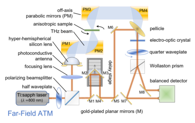
Original ATM techniques involve rotating the sample at the focal point of a linearly polarized THz beam using a mechanically rotated sample mount. For this reason, the configuration is typically a far-field instrument in which a balanced detector (sensitive to infrared light) is placed a considerable distance from the sample. In the terahertz time-domain spectroscopy configuration, both the infrared and THz beams are transmitted through an electro-optic (EO) crystal like ZnTe or GaP. Here, the infrared beam detects the change in birefringence of the EO crystal due to the THz beam. When a sample is placed in the THz beam, the polarized THz beam is perturbed and the resulting degree of birefringence in the EO crystal is changed. The resulting perturbation of the infrared beam is sensed at the balanced detector.

Rotated sample ATM is very useful for large samples (0.1 to 1 cm). However, when measuring samples such as protein crystals that must be isolated inside a hydration chamber, for example, the sample cannot be easily rotated. Additionally, it is challenging to maintain the same location of a rotated sample at the precise focal point of a THz beam.
Instrument Design
An ATM designed with a rotated sample is typically a far-field measurement configuration using a time-domain spectroscopy strategy.
A high power infrared laser is typically used. Its beam is split by a beamsplitter into two optical paths: a probe beam and a THz generation beam.
The THz generation beam typically receives the greater fraction of NIR power in order to maximize the power of the THz light commonly generated by a voltage-pulsed photoconductive antenna. The generated THz light is collected through a hyper-hemispherical silicon lens and passed to an off-axis parabolic mirror that collimates the THz beam for polarization by a THz polarizer that is often made of a simple wire-grid. The linearly polarized THz beam is then focused by a second off-axis parabolic mirror onto the sample. The THz beam transmitted through the sample is again collected by a third off-axis parabolic mirror, collimated onto a fourth parabolic mirror that then focuses the beam onto an electro-optic (EO) crystal whose birefringence is perturbed by the strength of the THz beam.
The NIR probe beam is passed through the EO crystal to probe the induced degree of birefringence caused by the THz beam and passed to a detection module that often consists of an NIR quarter wave plate, a Wollaston prism that spatially separates orthogonal polarization states of the probe beam into two optical paths that are individually detected at a balanced detector. The resulting signal reported by the balanced detector is a measure of the difference in magnitude of these two orthogonal components of the NIR probe beam and therefore a direct correlation of the degree of birefringence induced in the EO crystal by the THz beam passed through the sample.
Stationary Sample ATM
Previously called "ideal ATM" and "polarization-varying ATM," stationary sample ATM (SSATM) involves rotation of the linearly polarized state of the THz beam in a time-domain spectroscopy (TDS) configuration parallel to the interrogated material sample. In a SSATM configuration, the THz beam polarization is rotated through 360° in a plane perpendicular to the propagation direction of the beam. Measurements of the sample's anisotropy is measured at several THz polarization angles.
At least two methods to achieve THz polarization rotation for SSATM have been demonstrated: 1) by using a THz quarter waveplate (THz-QWP) together with an infrared polarizer and 2) by rotating the photoconductive antenna.
In the case of employing a THz-QWP and an infrared polarizer, the magnitude of the measured signal, , where is a time delay between THz generation and the detected pulses in a THz-TDS system is dependent on the relative polarization angle of the THz light, and the polarization angle of the ultrafast near-infrared (NIR) probe beam, , at the sample by the relationship The objective is to maintain equal magnitude of the THz electric field at the sample for all measurement angles, . This requires adjustment of for every .

Instrument Design
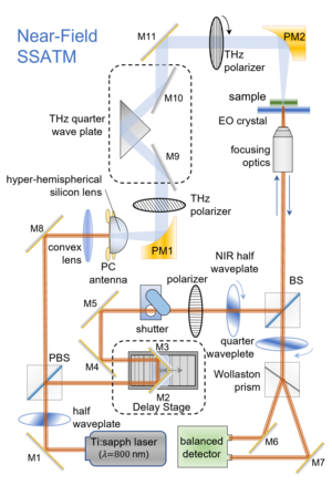
A SSATM instrument is typically designed in a time-domain spectroscopy configuration in which a high power infrared laser beam is divided into two optical paths by a beamsplitter.
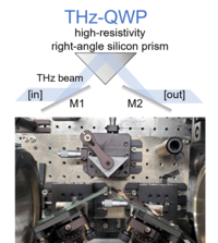
The first optical path often receives a greater fraction of the optical power of the laser to maximize the output power of generated THz light. THz light is often generated with a voltage-pulsed photoconductive antenna, collected with a hyper-hemispherical silicon lens, collimated using an off-axis parabolic mirror that is then passed through a THz polarizer, made circular by a THz quarter waveplate constructed of two planar mirrors and a right-angled high-resistivity silicon prism to form circularly polarized light. A second THz polarizer selects from the circularly polarized THz light the angle at which each measurement is made once the light reaches a sample located at a focal point of the beam and mounted in direct contact with an electro-optic crystal often made of either ZnTe or GaP.
The second optical path includes a retroreflector mirror mounted on a delay stage that adjusts the time-of-flight of the NIR beam to match the delay time, , of the THz light at the sample. The NIR beam is linearly polarized and chopped at a frequency suitable for detection, directed to the EO crystal to measure the change in its birefringence due to the degree of THz absorption by the sample. The NIR beam is reflected by the sample/EO crystal interface and directed to the detection module that often consists of an NIR quarter waveplate, a Wollaston prism that spatially selects perpendicular polarization states of the light toward two detectors in a balanced detector. The detected signal is a measure of the difference of the magnitude of the two perpendicular polarization states and corresponds to the degree of birefringence induced in the EO crystal by the THz light as-perturbed by the sample.
THz Quarter Waveplate
One strategy to provide full 360° rotation of THz polarization of equal electric field magnitude at the sample is to generate a circular state of polarization, then select particular linear polarization states from the circularly polarized beam with a THz polarizer.
A circular polarization state may be generated by a quarter waveplate, however, common optical waveplates are typically designed for visible, near- and mid-infrared regions of the electromagnetic spectrum. A quarter waveplate designed for use in the THz frequency range consists of a right-angle silicon prism together with metal-coated planar mirrors as input/output. In particular, the silicon prism acts analogously to a Fresnel rhomb with a single total internal reflection on the longer face of the prism and is a passive broadband component that permits a wide frequency sweep during measurements.

Advantages
A few advantages of ATM over other related microspectroscopy techniques include the orientation of the THz electric field at the sample and the ability to readily measure materials that are sensitive to environmental conditions like hydration, cryo-cooling, and evacuation.
THz polarization orientation at the sample
A key characteristic of ATM is the orientation of the polarized electric field of THz light at the sample. In particular, unlike other microspectroscopy techniques like scattering scanning near-field optical microscopy (s-SNOM), the electric field of the interrogating THz field is parallel to the surface of the sample. In s-SNOM, the shape of the oscillating metallic probe tip directs the THz polarization into a direction predominantly perpendicular to the sample surface.
Environmentally sensitive sample materials
Living organisms typically consist of large quantities of water. Many anisotropic materials of interest are biological in nature and as such require hydration during spectroscopic measurements. While some limited novel techniques to measure properties of materials inside a hydrated sample chamber have been recently reports, the primary design requirement of ATM is that the material is accessible through a window that is transparent to THz light such as quartz. Similarly, samples requiring cryo-cooling or low pressure vacuum environment are readily interrogated in ATM using THz-transparent window materials.
Applications
Anisotropic terahertz microspectrosopy (ATM) has found applications in structural biology and molecular fingerprinting of DNA and proteins. The technique is also suitable for drug discovery and studying THz frequency properties of thin film solid state materials.
Special attention is given to molecular motions in proteins where many structural changes occur at frequencies in the terahertz range of the spectrum (0.3 THz to 3 THz). These structural changes include hinge motions in which two regions of molecules are connected together by a flexible molecular structure that bends like a mechanical hinge or elbow. ATM is uniquely capable of measuring the spatial direction in which hinge motions occur because of its use of linearly polarized electric fields.
Protein dynamics
ATM is uniquely suited to measure resonant molecular vibrations in proteins. Molecular motions in proteins occur with frequencies in the terahertz range of the spectrum (0.3 THz to 3 THz). These structural changes include hinge motions in which two regions of molecules are connected together in a flexible way that bends like a mechanical hinge or joint and other conformational changes that occur within systems of protein molecules.
Protein molecules are typically surrounded by water molecules and are arranged in random orientations. For this reason, it is common to arrange protein molecules in crystal form such that their orientations all the same. In particular, in a protein crystal the dipole of all protein molecules are naturally aligned. This allows us to perform microspectroscopy with polarized THz light and ascertain the spatial orientation of vibrations within molecules.
References
- "The Optics Library". The Optics Library, Markelz Research Group. Tim LaFave Jr. Retrieved June 28, 2023.
- Niessen, K.; Deng, Y.; Markelz, A.G. (2019). "Near-field THz micropolarimetry". Optics Express. 27 (20): 28036–28047. Bibcode:2019OExpr..2728036N. doi:10.1364/OE.27.028036. PMC 6825620. PMID 31684561. S2CID 207896639.
- Deng, Y.; McKinney, J. A.; George, D. K.; Niessen, K. A.; Sharma, A.; Markelz, A.G. (2017). "Near-field stationary sample terahertz spectroscopic polarimetry for biomolecular structural dynamics determination". ACS Photonics. 8 (2): 658–668. doi:10.1021/acsphotonics.0c01876. S2CID 234045034.
- Mosley, C. D. W.; Failla, M.; Prabhakaran, D.; Lloyd-Hughes, J. (2017). "Terahertz spectroscopy of anisostropic materials using beams with rotatable polarization". Scientific Reports. 7 (1): 12337. Bibcode:2017NatSR...712337M. doi:10.1038/s41598-017-12568-0. PMC 5615066. PMID 28951590.
- Planken, P. C. M.; Nienhuys, H.-K.; Bakker, H. J.; Wenckebach, T. (2001). "Measurement and calculation of the orientation dependence of terahertz pulse detection in ZnTe". J. Opt. Soc. Am. B. 18 (3): 313−317. Bibcode:2001JOSAB..18..313P. doi:10.1364/JOSAB.18.000313.
- "The Optics Library". The Optics Library, Markelz Research Group. Tim LaFave Jr. Retrieved June 28, 2023.
- "The Optics Library". The Optics Library, Markelz Research Group. Tim LaFave Jr. Retrieved June 28, 2023.
- Niessen, K. A.; Xu, M.; George, D. K.; Chen, M. C.; Ferre-D-Amare, A. R.; Snell, E. H.; Cody, V.; Pace, J.; Schmidt, M.; Markelz, A. G. (2019). "Protein and RNA dynamical fingerprinting". Nature. 10 (1): 1026. Bibcode:2019NatCo..10.1026N. doi:10.1038/s41467-019-08926-3. PMC 6399446. PMID 30833555. S2CID 70350342.
- Acbas, G.; Niessen, K. A.; Snell, E. H.; Markelz, A. G. (2014). "Protein Optical measurements of long-range protein vibrations". Nature Communications. 5: 3076. doi:10.1038/ncomms4076. PMID 24430203.
 , where
  is a time delay between THz generation and the detected pulses in a THz-TDS system is dependent on the relative polarization angle of the THz light,
  and the polarization angle of the ultrafast near-infrared (NIR) probe beam,
  , at the sample by the relationship
 The objective is to maintain equal magnitude of the THz electric field at the sample for all measurement angles,