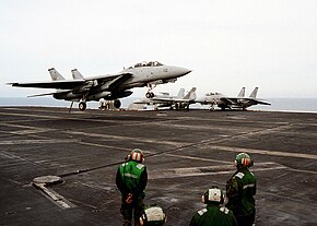
An arresting gear, or arrestor gear, is a mechanical system used to rapidly decelerate an aircraft as it lands. Arresting gear on aircraft carriers is an essential component of naval aviation, and it is most commonly used on CATOBAR and STOBAR aircraft carriers. Similar systems are also found at land-based airfields for expeditionary or emergency use. Typical systems consist of several steel wire ropes laid across the aircraft landing area, designed to be caught by an aircraft's tailhook. During a normal arrestment, the tailhook engages the wire and the aircraft's kinetic energy is transferred to hydraulic damping systems attached below the carrier deck. There are other related systems that use nets to catch aircraft wings or landing gear. These barricade and barrier systems are only used for emergency arrestments for aircraft without operable tailhooks.
History

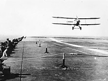
Arresting cable systems were invented by Hugh Robinson and were used by Eugene Ely on his first landing on a ship—the armored cruiser USS Pennsylvania, on 18 January 1911. These early systems had cables run through pulleys and attached to dead weights, such as sandbags. More modern arresting cables were tested on HMS Courageous in June 1931, designed by Commander C. C. Mitchell.
Modern U.S. Navy aircraft carriers have the Mark 7 Mod 3 arresting gear installed, which have the capability of recovering a 50,000-pound (23 t) aircraft at an engaging speed of 130 knots (240 km/h; 150 mph) in a distance of 344 feet (105 m) in two seconds. The system is designed to absorb theoretical maximum energy of 47.5 million foot-pounds (64.4 MJ) at maximum cable run-out.
Prior to the introduction of the angled flight deck, two systems were used (in addition to deck cables) to keep landing aircraft from running into parked aircraft further forward on the flight deck: the barrier and the barricade. If the aircraft tailhook failed to catch a wire, its landing gear would be caught by a 3-to-4-foot-high (0.9 to 1.2 m) net known as the barrier. If the aircraft caught a wire upon touchdown, the barrier could be quickly lowered to allow aircraft to taxi over it. The final safety net was the barricade, a large, 15-foot-high (5 m) net that prevented landing aircraft from crashing into other aircraft parked on the bow. Barriers are no longer in use, although ground-based arresting gear are sometimes called "barriers". Barricades are still in use aboard carriers, but they are only rigged and used in emergencies.
Operation

A normal arrestment is accomplished when the arresting hook of an incoming aircraft engages one of the deck pendants. When a landing aircraft engages a deck pendant, the force of the forward motion of the landing aircraft is transferred to a purchase cable, which is routed via sheaves to the arresting engine, located in a machinery room below the flight deck or on either side of the runway. As the deck pendant and the purchase cable are pulled out by the aircraft being arrested, the kinetic energy of the aircraft is transferred to mechanical energy of the cables, and the arresting engine transfers the mechanical energy of the cables to hydraulic energy. This classic system of hydraulic arrest is now being supplanted by one using electromagnetics where the energy absorption is controlled by a turbo-electric engine. The arresting engine brings about a smooth, controlled stop of the landing aircraft. At the completion of the arrestment, the aircraft arresting hook is disengaged from the deck pendant, which is then retracted to its normal position.
Sea-based systems

Modern carriers typically have three or four arresting cables laid across the landing area. All U.S. carriers in the Nimitz-class, along with Enterprise, have four wires, with the exception of USS Ronald Reagan and USS George H.W. Bush, which have only three. Gerald R. Ford-class carriers will also have three. Pilots aim for the second wire for the three-wire configuration or third wire for the four-wire configuration to reduce the risk of landing short. Aircraft coming in to land on a carrier are at approximately 85% of full throttle. At touchdown, the pilot advances the throttles to Military (MIL) power. In the F/A-18E/F Super Hornet and EA-18G Growler aircraft, the aircraft automatically reduces engine thrust to 70% once the deceleration of a successful arrestment is detected. This feature can be overridden by the pilot by selecting max afterburner. If the aircraft fails to catch an arresting cable, a condition known as a "bolter", the aircraft has sufficient power to continue down the angled flight deck and become airborne again. Once the arresting gear stops the aircraft, the pilot brings the throttles back to idle, raises the hook and taxies clear.
In addition to American CVNs (nuclear aircraft carriers), the French Charles de Gaulle, the Russian Admiral Kuznetsov, the Chinese Liaoning, Shandong and Fujian as well as the Indian Vikramaditya and Vikrant are active or future aircraft carriers installed with arresting gear.
Land-based systems

Land-based military airfields operating fighter or jet trainer aircraft also use arresting gear systems, although they are not required for all landings. Instead, they are used for landing aircraft on short or temporary runways, or for emergencies involving brake failure, steering problems or other situations in which using the full length of the runway is not possible or safe. There are three basic types of land based systems: permanent, expeditionary, and overrun gear.

Permanent systems are installed on nearly all U.S. military airfields operating fighter or jet trainer aircraft. Expeditionary systems are similar to permanent systems and are used for landing aircraft on short or temporary runways. Expeditionary systems are designed to be installed or uninstalled in only a few hours.
Overrun gear consisting of hook cables or elastic nets known as barriers are commonly used as a backup system. Barrier nets catch the wings and fuselage of an aircraft and use an arresting engine or other methods such as anchor chains or bundles of woven textile material to slow the aircraft down. On some land-based airfields where the overrun area is short, a series of concrete blocks referred to as an engineered materials arrestor system (EMAS) is used. These materials are used to catch the landing gear of an aircraft and slow it via rolling resistance and friction. Aircraft are stopped by the transfer of energy required to crush the blocks. Unlike other types of arresting gear, EMAS is also used at some civilian airports where the overrun area is shorter than would normally be allowed.
The first use of a barrier on a military airfield was during the Korean War when jet fighters had to operate from shorter airfields where there was no margin for error. The system used was just a transplant of the Davis Barrier used on straight deck carriers to keep any aircraft that missed the arrest wires from crashing into the aircraft parked forward of the landing area. But instead of the more complex hydraulic system used on carriers to stop the aircraft when it hits the barrier the land based system used heavy ship anchor chains to bring the aircraft to a halt.
Components

The major systems that make up typical arresting gear are the hook cable or pendants, purchase cables or tapes, sheaves, and arresting engines.
Cross-deck pendant

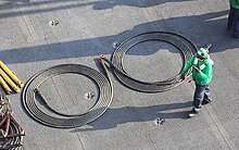
Also known as arresting cables or wires, cross-deck pendants are flexible steel cables that are spanned across the landing area to be engaged by the arresting hook of an incoming aircraft. On aircraft carriers there are either three or four cables, numbered 1–4 from aft to forward. Pendants are made of wire rope with a diameter of 1, 1+1⁄4 or 1+3⁄8 inches (25, 32 or 35 mm). Each wire rope is made up of numerous strands twisted about an oiled hemp center core, which provides a "cushion" for each strand and also supplies cable lubrication. The cable ends are equipped with terminal couplings designed for quick detachment during replacement and are able to be rapidly detached and replaced (in about 2–3 minutes on aircraft carriers). On U.S. carriers, the arresting cables are removed and replaced after each 125 arrested landings. Individual cables are often removed and left "stripped" in order to perform maintenance on other components of the arresting gear during aircraft recoveries (using other, on line, systems). Wire supports raise the deck pendants several inches so that they may be picked up by the tailhook of a landing aircraft. The wire supports on carriers are merely curved steel leaf springs that can flex to allow an aircraft to taxi over the installed deck pendant. On land based systems, 6-inch (15 cm) diameter "donut"-shaped rubber supports raise the cable off the runway surface approximately 3 inches (7.5 cm).
Purchase cables or tapes
The purchase cable is a wire rope that looks very similar to the arresting cable. They are much longer, however, and are not designed to be easily removed. There are two purchase cables per arresting cable, and they connect to each end of the arresting wire. Purchase cables connect the arresting wire to the arresting gear engines and "pay out" as the arresting wire is engaged by the aircraft. As an incoming aircraft engages the deck pendant, the purchase cable transmits the force of the landing aircraft from the deck gear to the arresting engine. The pendant (arresting wire) is "swaged" (attached) to the purchase cable by means of a loop created with zinc heated to 1,000 °F (540 °C). This onboard fabrication is considered dangerous, and it is reported the US Navy is testing the use of an automated press to accomplish it more safely. On land based systems, heavy nylon tapes are used in place of purchase cables, but they serve the same function.
Sheaves
Purchase cables or tapes run through sheaves in the flight deck or alongside of the runway to the arresting engines. Damper sheaves act as hydraulic shock absorbers that provide for the increased landing speeds.
Spray-type arrest gear
In 1957 the concept of a piston being pulled through a tube of water was first purposed as a cheap arrest gear system for land airbases. In the early 1960s, the British took this basic concept and developed a spray-type arrest gear system for both land and sea use. The engine had hydraulic cylinders that moved through water filled pipe, with a smaller pipe alongside that has holes of various size along its length. The Royal Navy claimed that there was no theoretical weight limit, but there was a speed limit.
Arresting engines

Each pendant has its own engine systems that absorb and dispel the energies developed when a landing aircraft is arrested. On American Nimitz-class carriers, hydro-pneumatic systems are used, each weighing 43 short tons (39 t), wherein oil is hydraulically forced out of a cylinder by a ram connected to the purchase cable, through a control valve. A major development in arresting gear was the constant runout control valve, which controls the fluid flow from the engine cylinder to the accumulator and is designed to stop all aircraft with the same amount of runout regardless of mass and speed. The aircraft's weight is set by each arresting gear engine's operator. During normal operations, a "single weight setting" is used for simplicity. This weight is usually the maximum landing, or "max trap", weight for the aircraft. In certain cases, usually aircraft malfunctions, which affect approach speed, a "single weight setting" is used to ensure proper energy absorption by the system. The operator is given the weight of the aircraft by the air officer in Primary Flight Control. The operator then sets the constant runout control valve to the appropriate weight setting for that aircraft. The pressure setting for the arresting gear engine remains at a constant pressure of about 400 psi (2,800 kPa). The constant runout valve (CROV) stops the aircraft, as opposed to hydraulic pressure.
Permanent and expeditionary land based systems usually consist of two arresting engines located on either side of the runway. The arresting engines apply braking force to reels holding the purchase tapes, which in turn slow the aircraft and bring it to a stop. The two most common methods used by land based arresting engines to apply the braking force are the rotary friction brake and the rotary hydraulic, or "water twister", systems. The rotary friction brake is simply a hydraulic pump coupled to the reel, which applies a graduated pressure to multi-disc brakes mounted on the reel. The rotary hydraulic system is a turbine inside a water/glycol-filled housing coupled to the reel. The turbulence generated in the water/glycol mixture by the turbine during the arrestment provides the resistance to slow the reel and stop the aircraft. Once the aircraft is released from the cable, the tapes and cable are retracted by an internal combustion engine or electric motor installed on the arresting engine.
Excessive runout during an arrestment is a condition known as a "two-block." This name is derived from naval parlance when all the line has been pulled through a pulley system, the two pulley blocks are touching, hence "two blocked". Excessive runout can be caused by improper arresting gear settings, excess aircraft gross weight, excess aircraft engagement speed, or excess airplane thrust applied during the arrestment. Off center landings also have the danger of damaging the arresting gear.
Advanced Arresting Gear landing system
Main article: Advanced Arresting GearElectromagnets are being used in the new Advanced Arresting Gear (AAG) system on American aircraft carriers. The current system (above) relies on hydraulics to slow and stop a landing aircraft. While the hydraulic system is effective, as demonstrated by more than fifty years of implementation, the AAG system offers a number of improvements. The current system is unable to capture unmanned aerial vehicles (UAVs) without damaging them due to extreme stresses on the airframe. UAVs do not have the necessary mass to drive the large hydraulic piston used to trap heavier, manned airplanes. By using electromagnetics the energy absorption is controlled by a turbo-electric engine. This makes the trap smoother and reduces shock on airframes. Even though the system will look the same from the flight deck as its predecessor, it will be more flexible, safe, and reliable, and will require less maintenance and manning. This system is being trialed on the USS Gerald R. Ford and will be installed on all of the Gerald R. Ford-class aircraft carriers.
Barricade


The barricade is an emergency recovery system used only when a normal (pendant) arrestment cannot be made. The barricade is normally in a stowed condition and rigged only when required. To rig a barricade, it is stretched across the flight deck between stanchions, which are raised from the flight deck. Rigging the barricade is routinely practiced by U.S. carrier flight deck personnel; a well trained crew can accomplish the task in under three minutes.
The barricade webbing consists of upper and lower horizontal loading straps joined to each other at the ends. Five vertical engaging straps, spaced 20 feet (6 m) apart, are connected to each upper and lower load strap. The barricade webbing is raised to a height of approximately 20 feet. The barricade webbing engages the wings of the landing aircraft, wherein energy is transmitted from the barricade webbing through the purchase cable to the arresting engine. Following a barricade arrestment, the webbing and deck cables are discarded and the stanchions are lowered back into their recessed slots. Barricade engagements are rare, as tailhooks are designed to be extremely fail-safe, and an aircraft returning from combat with such severe damage would likely not be able to land. This device has been installed on all American aircraft carriers and on the French Charles de Gaulle, while Brazilian CATOBAR and Russian and Indian STOBAR aircraft carriers have only conventional arresting gear installed.
See also
- Aircraft catapult
- Aviation-capable naval vessel
- Brodie landing system
- Modern US Navy carrier air operations
- Engineered materials arrestor system - a system to limit the severity of a runway excursion
References
- "C. C. Mitchell". Graces Guide.
- ^ Mola, Roger (June–July 2015). "An Aircraft Carrier's Cable Guys". Air & Space. Retrieved 10 May 2018.
- Keegan, John (1989). The Price of Admiralty. New York: Viking. p. 276. ISBN 0-670-81416-4.
- "OK two wire! Ronald Reagan (CVN 76) ramps up new technology". thefreelibrary.com. 1 July 2002.
- Hearst Magazines (May 1954). "'Tennis Net' Crash Barrier Halts Jets at End of Runway". Popular Mechanics. Hearst Magazines. p. 127.
- ^ "Aviation Boatswain's. Mate E. NAVEDTRA 14310 (Nonresident Training Course)" (PDF). GlobalSecurity.org. Naval Education and Training Professional Development and Technology Center. July 2001. Archived from the original (PDF) on 18 October 2014.
- CV NATOPS, pp. 6–8.
- "Runway Arrestor Gear Systems - SKYbrary Aviation Safety". skybrary.aero. Retrieved 5 September 2021.
- "New Jet-landing Method Permits Aircraft to Stop Within 100 Yard". Popular Mechanics. Hearst Magazines. April 1957. p. 119.
- "World News – Spray Type Arrest Gear" Flight International, 9 August 1962.
- Rodriguez, Carmelo. "Launch and Recovery Testing". ITEA-SAN. Turboelectric Arresting Gear. Mission Valley Hotel, San Diego. 16 June 2005.
External links
- Successful wheels up landing of F-111C at Royal Australian Air Force base Amberley – Series of photographs depicting a RAAF F-111 landing with land-based arresting cables following a landing gear failure.
- Landing on an aircraft carrier – How stuff works