| This article includes a list of general references, but it lacks sufficient corresponding inline citations. Please help to improve this article by introducing more precise citations. (January 2024) (Learn how and when to remove this message) |

Force control is the control of the force with which a machine or the manipulator of a robot acts on an object or its environment. By controlling the contact force, damage to the machine as well as to the objects to be processed and injuries when handling people can be prevented. In manufacturing tasks, it can compensate for errors and reduce wear by maintaining a uniform contact force. Force control achieves more consistent results than position control, which is also used in machine control. Force control can be used as an alternative to the usual motion control, but is usually used in a complementary way, in the form of hybrid control concepts. The acting force for control is usually measured via force transducers or estimated via the motor current.
Force control has been the subject of research for almost three decades and is increasingly opening up further areas of application thanks to advances in sensor and actuator technology and new control concepts. Force control is particularly suitable for contact tasks that serve to mechanically process workpieces, but it is also used in telemedicine, service robot and the scanning of surfaces.
For force measurement, force sensors exist that can measure forces and torques in all three spatial directions. Alternatively, the forces can also be estimated without sensors, e.g. on the basis of the motor currents. Indirect force control by modeling the robot as a mechanical resistance (impedance) and direct force control in parallel or hybrid concepts are used as control concepts. Adaptive approaches, fuzzy controllers and machine learning for force control are currently the subject of research.
General

Controlling the contact force between a manipulator and its environment is an increasingly important task in the environment of mechanical manufacturing, as well as industrial and service robot. One motivation for the use of force control is safety for man and machine. For various reasons, movements of the robot or machine parts may be blocked by obstacles while the program is running. In service robot these can be moving objects or people, in industrial robotics problems can occur with cooperating robots, changing work environments or an inaccurate environmental model. If the trajectory is misaligned in classical motion control and thus it is not possible to approach the programmed robot pose(s), the motion control will increase the manipulated variable - usually the motor current - in order to correct the position error. The increase of the manipulated variable can have the following effects:
- The obstacle is removed or damaged/destroyed.
- The machine is damaged or destroyed.
- The manipulated variable limits are exceeded and the robot controller switches off.
A force control system can prevent this by regulating the maximum force of the machine in these cases, thus avoiding damage or making collisions detectable at an early stage.
In mechanical manufacturing tasks, unevenness of the workpiece often leads to problems with motion control. As can be seen in the adjacent figure, surface unevenness causes the tool to penetrate too far into the surface during position control (red) or lose contact with the workpiece during position control (red) . This results, for example, in an alternating force effect on the workpiece and tool during grinding and polishing. Force control (green) is useful here, as it ensures uniform material removal through constant contact with the workpiece.
Application
In force control, a basic distinction can be made between applications with pronounced contact and applications with potential contact. We speak of pronounced contact when the contact of the machine with the environment or the workpiece is a central component of the task and is explicitly controlled. This includes, above all, tasks of mechanical deformation and surface machining. In tasks with potential contact, the process function variable is the positioning of the machine or its parts. Larger contact forces between machine and environment occur due to dynamic environment or inaccurate environment model. In this case, the machine should yield to the environment and avoid large contact forces.

The main applications of force control today are mechanical manufacturing operations. This means in particular manufacturing tasks such as grinding, polishing and deburring as well as force-controlled processes such as controlled joining, bending and pressing of bolts into prefabricated bores. Another common use of force control is scanning unknown surfaces. Here, force control is used to set a constant contact pressure in the normal direction of the surface and the scanning head is moved in the surface direction via position control. The surface can then be described in Cartesian coordinates via direct kinematics.
Other applications of force control with potential contact can be found in medical technology and cooperating robots. Robots used in telemedicine, i.e. robot-assisted medical operations, can avoid injuries more effectively via force control. In addition, direct feedback of the measured contact forces to the operator by means of a force feedback control device is of great interest here. Possible applications for this extend to internet-based teleoperations.
In principle, force control is also useful wherever machines and robots cooperate with each other or with humans, as well as in environments where the environment is not described exactly or is dynamic and cannot be described exactly. Here, force control helps to deal with obstacles and deviations in the environmental model and to avoid damage.
History
The first important work on force control was published in 1980 by John Kenneth Salisbury at Stanford University. In it, he describes a method for active stiffness control, a simple form of impedance control. However, the method does not yet allow a combination with motion control, but here force control is performed in all spatial directions. The position of the surface must therefore be known. Because of the lower performance of robot controllers of that time, force control could only be performed on mainframe computers. Thus, a controller cycle of ≈100 ms was achieved.
In 1981, Raibert and Craig presented a paper on hybrid force/position control which is still important today. In this paper, they describe a method in which a matrix (separation matrix) is used to explicitly specify for all spatial directions whether motion or force control is to be used. Raibert and Craig merely sketch the controller concepts and assume them to be feasible.
In 1989, Koivo presented an extended exposition of the concepts of Raibert and Craig. Precise knowledge of the surface position is still necessary here, which still does not allow for the typical tasks of force control today, such as scanning surfaces.
Force control has been the subject of intense research over the past two decades and has made great strides with the advancement of sensor technology and control algorithms. For some years now, the major automation technology manufacturers have been offering software and hardware packages for their controllers to allow force control. Modern machine controllers are capable of force control in one spatial direction in real time computing with a cycle time of less than 10 ms.
Force measurement
Main article: Force measurementTo close the force control loop in the sense of a closed-loop control, the instantaneous value of the contact force must be known. The contact force can either be measured directly or estimated.
Direct force measurement

The trivial approach to force control is the direct measurement of the occurring contact forces via force/torque sensors at the end effector of the machine or at the wrist of the industrial robot. Force/torque sensors measure the occurring forces by measuring the deformation at the sensor. The most common way to measure deformation is by means of strain gauges.
In addition to the widely used strain gauges made of variable electrical resistances, there are also other versions that use piezoelectric, optical or capacitive principles for measurement. In practice, however, they are only used for special applications. Capacitive strain gages, for example, can also be used in the high-temperature range above 1000 °C.
Strain gages are designed to have as linear a relationship as possible between strain and electrical resistance within the working space. In addition, several possibilities exist to reduce measurement errors and interference. To exclude temperature influences and increase measurement reliability, two strain gauges can be arranged in a complementary manner.
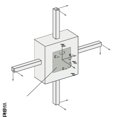
Modern force/torque sensors measure both forces and torques in all three spatial directions and are available with almost any value range. The accuracy is usually in the per mil range of the maximum measured value. The sampling rates of the sensors are in the range of about 1 kHz. An extension of the 6-axis force/torque sensors are 12- and 18-axis sensors which, in addition to the six force or torque components, are also capable of measuring six velocity and acceleration components each.
Six-axis force/torque sensor

In modern applications, so-called six-axis force/torque sensors are frequently used. These are mounted between the robot hand and the end effector and can record both forces and torques in all three spatial directions. For this purpose, they are equipped with six or more strain gauges (possibly strain measurement bridges) that record deformations in the micrometer range. These deformations are converted into three force and torque components each via a calibration matrix.
Force/torque sensors contain a digital signal processor that continuously acquires and filters the sensor data (strain) in parallel, calculates the measurement data (forces/torques) and makes it available via the sensor's communication interface.
The measured values correspond to the forces at the sensor and usually still have to be converted into the forces and torques at the end effector or tool via a suitable transformation.
Since force/torque sensors are still relatively expensive (between €4,000 and €15,000) and very sensitive to overloads and disturbances, they - and thus force control - have been reluctantly used in industry. Indirect force measurement or estimation is one solution, allowing force control without costly and disturbance-prone force sensors.
Force estimation
A cost-saving alternative to direct force measurement is force estimation (also known as "indirect force measurement"). This makes it possible to dispense with the use of force/torque sensors. In addition to cost savings, dispensing with these sensors has other advantages: Force sensors are usually the weakest link in the mechanical chain of the machine or robot system, so dispensing with them brings greater stability and less susceptibility to mechanical faults. In addition, dispensing with force/torque sensors brings greater safety, since there is no need for sensor cables to be routed out and protected directly at the manipulator's wrist.
A common method for indirect force measurement or force estimation is the measurement of the motor currents applied for motion control. With some restrictions, these are proportional to the torque applied to the driven robot axis. Adjusted for gravitational, inertial and frictional effects, the motor currents are largely linear to the torques of the individual axes. The contact force at the end effector can be determined via the torques thus known.
Separation of dynamic and static forces
During force measurement and force estimation, filtering of the sensor signals may be necessary. Numerous side effects and secondary forces can occur which do not correspond to the measurement of the contact force. This is especially true if a larger load mass is mounted on the manipulator. This interferes with the force measurement when the manipulator moves with high accelerations.
To be able to adjust the measurement for side effects, both an accurate dynamic model of the machine and a model or estimate of the load must be available. This estimate can be determined via reference movements (free movement without object contact). After estimating the load, the measurement or estimate of the forces can be adjusted for Coriolis, centripetal and centrifugal forces, gravitational and frictional effects, and inertia. Adaptive approaches can also be used here to continuously adjust the estimate of the load.
Control concepts
Various control concepts are used for force control. Depending on the desired behavior of the system, a distinction is made between the concepts of direct force control and indirect control via specification of compliance or mechanical impedance. As a rule, force control is combined with motion control. Concepts for force control have to consider the problem of coupling between force and position: If the manipulator is in contact with the environment, a change of the position also means a change of the contact force.
Impedance control
Impedance control, or compliance control, regulates the compliance of the system, i.e., the link between force and position upon object contact. Compliance is defined in the literature as a "measure of the robot's ability to counteract contact forces." There are passive and active approaches to this. Here, the compliance of the robot system is modeled as mechanical impedance, which describes the relationship between applied force and resulting velocity. Here, the robot's machine or manipulator is considered as a mechanical resistance with positional constraints imposed by the environment. Accordingly, the causality of mechanical impedance describes that a movement of the robot results in a force. In mechanical admittance, on the other hand, a force applied to the robot results in a resulting motion.
Passive impedance control

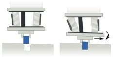
Passive compliance control (also known as compliance control) does not require force measurement because there is no explicit force control. Instead, the manipulator and/or end effector is flexibly designed in a way that can minimize contact forces that occur during the task to be performed. Typical applications include insertion and gripping operations. The end effector is designed in such a way that it allows translational and rotational deviations orthogonal to the gripping or insertion direction, but has high stiffness in the gripping or insertion direction. The figure opposite shows a so-called Remote Center of Compliance (RCC) that makes this possible. As an alternative to an RCC, the entire machine can also be made structurally elastic.
Passive impedance control is a very good solution in terms of system dynamics, since there are no latency due to the control. However, passive compliance control is often limited by the mechanical specification of the end effector in the task and cannot be readily applied to different and changing tasks or environmental conditions.
Active impedance control
Active compliance control refers to the control of the manipulator based on a deviation of the end effector. This is particularly suitable for guiding robots by an operator, for example as part of a teach-in process.
Active compliance control is based on the idea of representing the system of machine and environment as a spring-damper-mass system. The force and the motion (position , velocity , and acceleration are directly related via the spring-damper-mass equation:
The compliance or mechanical impedance of the system is determined by the stiffness , the damping and the inertia and can be influenced by these three variables. The control is given a mechanical target impedance via these three variables, which is achieved by the machine control.

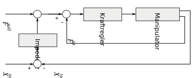
The figure shows the block diagram of a force-based impedance control. The impedance in the block diagram represents the mentioned components L, A and . A position-based impedance control can be designed analogously with internal position or motion control.
Alternatively and analogously, the compliance (admittance) can be controlled instead of the resistance. In contrast to the impedance control, the admittance appears in the control law as the reciprocal of the impedance.
Direct force control
The above concepts are so-called indirect force control, since the contact force is not explicitly specified as a command variable, but is determined indirectly via the controller parameters damping, stiffness and (virtual) mass. Direct force control is presented below.
Direct force control uses the desired force as a setpoint within a closed control loop. It is implemented as a parallel force/position control in the form of a cascade control or as a hybrid force/position control in which switching takes place between position and force control.
Parallel force/position control
One possibility for force control is parallel force/position control. The control is designed as a cascade control and has an external force control loop and an internal position control loop. As shown in the following figure, a corresponding infeed correction is calculated from the difference between the nominal and actual force. This infeed correction is offset against the position command values, whereby in the case of the fusion of and , the position command of force control ( )has a higher priority, i.e. a position error is tolerated in favor of the correct force control. The offset value is the input variable for the inner position control loop.

Analogous to an inner position control, an inner velocity control can also take place, which has a higher dynamic. In this case, the inner control loop should have a saturation in order not to generate a (theoretically) arbitrarily increasing velocity in the free movement until contact is made.
Hybrid force/position control
An improvement over the above concepts is offered by hybrid force/position control, which works with two separate control systems and can also be used with hard, inflexible contact surfaces. In hybrid force/position control, the space is divided into a constrained and an unconstrained space. The constrained space contains restrictions, for example in the form of obstacles, and does not allow free movement; the unconstrained space allows free movement. Each dimension of the space is either constrained or unconstrained.

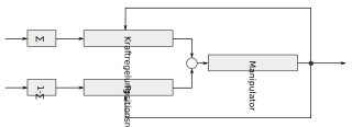
In hybrid force control, force control is used for the restricted space, and position control is used for the unrestricted space. The figure shows such a control. The matrix Σ indicates which space directions are restricted and is a diagonal matrix consisting of zeros and ones.
Which spatial direction is restricted and which is unrestricted can, for example, be specified statically. Force and position control is then explicitly specified for each spatial direction; the matrix Σ is then static. Another possibility is to switch the matrix Σ dynamically on the basis of force measurement. In this way, it is possible to switch from position control to force control for individual spatial directions when contact or collision is established. In the case of contact tasks, all spatial directions would be motion-controlled in the case of free movement, and after contact is established, the contact direction would be switched to force control by selecting the appropriate matrix Σ.
Research
In recent years, the subject of research has increasingly been adaptive concepts, the use of fuzzy control system and machine learning, and force-based whole-body control.
Adaptive force control
The previously mentioned, non-adaptive concepts are based on an exact knowledge of the dynamic process parameters. These are usually determined and adjusted by experiments and calibration. Problems can arise due to measurement errors and variable loads. In adaptive force control, position-dependent and thus time-variable parts of the system are regarded as parameter fluctuations and are constantly adapted in the course of the control by adaptation.
Due to the changing control, no guarantee can be given for dynamic stability of the system. Adaptive control is therefore usually first used offline and the results are intensively tested in simulation before being used on the real system.
Fuzzy control and machine learning
A prerequisite for the application of classical design methods is an explicit system model. If this is difficult or impossible to represent, fuzzy controllers or machine learning can be considered. By means of fuzzy logic, knowledge acquired by humans can be converted into a control behavior in the form of fuzzy control specifications. Explicit specification of the controller parameters is thus no longer necessary.
Approaches using machine learning, moreover, no longer require humans to create the control behavior, but use machine learning as the basis for control.
Whole body control
Due to the high complexity of modern robotic systems, such as humanoid robots, a large number of actuated degrees of freedom must be controlled. In addition, such systems are increasingly used in the direct environment of humans. Accordingly, concepts from force and impedance control are specifically used in this area to increase safety, as this allows the robot to interact with the environment and humans in a compliant manner.
References
- ^ Rusin, Vadym (2007). "Adaptive control of robotic systems in contact tasks" (PDF). Otto von Guericke University Magdeburg. Archived from the original (PDF) on 2016-01-09.
- Salisbury, John Kenneth (1980). Active Stiffness Control of a Manipulator in Cartesian Coordinates. 19th IEEE Conference on Decision and Control.
- ^ Dapper, Marcus (2003). Kraftsensorlose Manipulator Kraftsteuerung zur Abtastung unbekannter, harter Oberflächen. University of Bonn
- Raibert, M. H.; Craig, John (1981). "Hybrid Position/Force Control of Manipulators". Journal of Dynamic Systems, Measurement, and Control. 103 (2): 126–133. doi:10.1115/1.3139652.
- Koivo, A. J. (1989). Fundamentals for Control of Robotic Manipulators. New York, USA: Wiley & Sons.
- Cabaravdic, Malik (2008). Beitrag zur Optimierung des Spanvolumens beim industrierobotergestützten Bandschleifen frei geformter Werkstücke. Technische Universität Dortmund. p. 110.
- Suprijadi, Eko Bono (2005). Kinematische Echtzeit-Regelung und auf vereinfachter Kinematik basierte Kraftregelung einer vierbeinigen Gehmaschine. Universität Duisburg-Essen.
- Simpson, John; Li, Zheng; Cook, Chris (2022). "Sensorless Force Estimation for Robots with Friction" (PDF). Archived (PDF) from the original on 2024-01-30. Retrieved 2023-08-17.
- Colombo, D.; Dallefrate, D.; Tosatti, L. Molinari (2006). "PC Based Control Systems for Compliance Control and Intuitive Programming of Industrial Robots". ResearchGate.
- Siciliano, Bruno; Sciavicco, Lorenzo (2009). Robotics: modelling, planning and control. London: Springer. p. 364. ISBN 978-1-84628-641-4.
- Winkler, Alexander (2006). Ein Beitrag zur kraftbasierten Mensch-Roboter-Interaktion. Technischen Universität Chemnitz.
- Sciavicco, Lorenzo; Siciliano, Bruno (1999). Modelling and Control of Robot Manipulators (2 ed.). Springer. ISBN 1-85233-221-2.
- Dietrich, Alexander (2016). Whole-Body Impedance Control of Wheeled Humanoid Robots. Springer International Publishing. ISBN 978-3-319-40556-8.
Bibliography
- Bruno Siciliano, Luigi Villani (2000), Robot Force Control, Springer, ISBN 0-7923-7733-8
- Wolfgang Weber (2002), Industrieroboter. Methoden der Steuerung und Regelung, Fachbuchverlag Leipzig, ISBN 3-446-21604-9
- Lorenzo Sciavicco, Bruno Siciliano (1999), Modelling and Control of Robot Manipulators, Springer, ISBN 1-85233-221-2
- Klaus Richter (1991), Kraftregelung elastischer Roboter, VDI-Verlag, ISBN 3-18-145908-9
 or lose contact with the workpiece during position control (red)
  . This results, for example, in an alternating force effect on the workpiece and tool during grinding and polishing. Force control (green) is useful here, as it ensures uniform material removal through constant contact with the workpiece.
 and the motion (position
  , velocity
  , and acceleration
  are directly related via the spring-damper-mass equation:

 , the damping
  and the inertia
  and can be influenced by these three variables. The control is given a mechanical target impedance via these three variables, which is achieved by the machine control.
 and the position
  .
. , the position command of force control (