| This article needs additional citations for verification. Please help improve this article by adding citations to reliable sources. Unsourced material may be challenged and removed. Find sources: "Nanoindenter" – news · newspapers · books · scholar · JSTOR (May 2009) (Learn how and when to remove this message) |

A nanoindenter is the main component for indentation hardness tests used in nanoindentation. Since the mid-1970s nanoindentation has become the primary method for measuring and testing very small volumes of mechanical properties. Nanoindentation, also called depth sensing indentation or instrumented indentation, gained popularity with the development of machines that could record small load and displacement with high accuracy and precision. The load displacement data can be used to determine modulus of elasticity, hardness, yield strength, fracture toughness, scratch hardness and wear properties.
Types


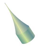
There are many types of nanoindenters in current use differing mainly on their tip geometry. Among the numerous available geometries are three and four sided pyramids, wedges, cones, cylinders, filaments, and spheres. Several geometries have become a well established common standard due to their extended use and well known properties; such as Berkovich, cube corner, Vickers, and Knoop nanoindenters. To meet the high precision required, nanoindenters must be made following the definitions of ISO 14577-2, and be inspected and measured with equipment and standards traceable to the National Institute of Standards and Technology (NIST). The tip end of the indenter can be made sharp, flat, or rounded to a cylindrical or spherical shape. The material for most nanoindenters is diamond and sapphire, although other hard materials can be used such as quartz, silicon, tungsten, steel, tungsten carbide and almost any other hard metal or ceramic material. Diamond is the most commonly used material for nanoindentation due to its properties of hardness, thermal conductivity, and chemical inertness. In some cases electrically conductive diamond may be needed for special applications and is also available.
Holders
Nanoindenters are mounted on holders which could be the standard design from a manufacturer of nanoindenting equipment, or custom design. The holder material can be steel, titanium, machinable ceramic, other metals or rigid materials. In most cases the indenter is attached to the holder using a rigid metal bonding process. The metal forms a molecular bond with both material be it diamond-steel, diamond-ceramic, etc.
Angular measurements
Nanoindenter dimensions are very small, some less than 50 micrometres (0.0020 in), and made with precise angular geometry in order to achieve the highly accurate readings required for nanoindentation. Instruments that measure angles on larger objects such as protractors or comparators are neither practical nor precise enough to measure nanoindenter angles even with help of microscopes. For precise measurements a laser goniometer is used to measure diamond nanoindenter angles. Nanoindenter faces are highly polished and reflective which is the basis for the laser goniometer measurements. The laser goniometer can measure within a thousandth of a degree to specified or requested angles.
References
- Nanoindentation Lecture 1 Basic Principle, by Do Kyung Kim, Dept. of Material Science and Engineering KAIST, Korea.
- Fischer-Cripps, A.C. Nanoindentation. (Springer: New York), 2004.
- W.C. Oliver and G.M. Pharr. An improved technique for determining hardness and elastic modulus using load and displacement sensing indentation experiments, J. Mater. Res., vol. 7, No. 6, June 1992.
- ISO 14577-2 = Instrumented indentation test for hardness and materials parameters. Part 2: Verification and calibration of testing machines. Section 4: Direct verification and calibration.
- "Archived copy" (PDF). Archived from the original (PDF) on 2015-12-23. Retrieved 2015-11-16.
{{cite web}}: CS1 maint: archived copy as title (link)