| Passband modulation |
|---|
 |
| Analog modulation |
| Digital modulation |
| Hierarchical modulation |
| Spread spectrum |
| See also |
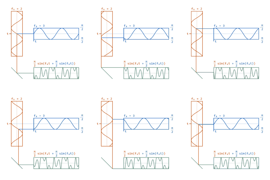
Phase modulation (PM) is a modulation pattern for conditioning communication signals for transmission. It encodes a message signal as variations in the instantaneous phase of a carrier wave. Phase modulation is one of the two principal forms of angle modulation, together with frequency modulation.
In phase modulation, the instantaneous amplitude of the baseband signal modifies the phase of the carrier signal keeping its amplitude and frequency constant. The phase of a carrier signal is modulated to follow the changing signal level (amplitude) of the message signal. The peak amplitude and the frequency of the carrier signal are maintained constant, but as the amplitude of the message signal changes, the phase of the carrier changes correspondingly.
Phase modulation is an integral part of many digital transmission coding schemes that underlie a wide range of technologies like Wi-Fi, GSM and satellite television. However it is not widely used for transmitting analog audio signals via radio waves. It is also used for signal and waveform generation in digital synthesizers, such as the Yamaha DX7, to implement FM synthesis. A related type of sound synthesis called phase distortion is used in the Casio CZ synthesizers.
Foundation
In general form, an analog modulation process of a sinusoidal carrier wave may be described by the following equation:
- .
A(t) represents the time-varying amplitude of the sinusoidal carrier wave and the cosine-term is the carrier at its angular frequency , and the instantaneous phase deviation . This description directly provides the two major groups of modulation, amplitude modulation and angle modulation. In amplitude modulation, the angle term is held constant, while in angle modulation the term A(t) is constant and the second term of the equation has a functional relationship to the modulating message signal.
The functional form of the cosine term, which contains the expression of the instantaneous phase as its argument, provides the distinction of the two types of angle modulation, frequency modulation (FM) and phase modulation (PM).

In FM the message signal causes a functional variation of the carrier frequency. These variations are controlled by both the frequency and the amplitude of the modulating wave.
In phase modulation, the instantaneous phase deviation (phase angle) of the carrier is controlled by the modulating waveform, such that the principal frequency remains constant.
In principle, the modulating signal in both frequency and phase modulation may either be analog in nature, or it may be digital.
The mathematics of the spectral behaviour reveals that there are two regions of particular interest:
- For small amplitude signals, PM is similar to amplitude modulation (AM) and exhibits its unfortunate doubling of baseband bandwidth and poor efficiency.
- For a single large sinusoidal signal, PM is similar to FM, and its bandwidth is approximately
- ,
Modulation index
As with other modulation indices, this quantity indicates by how much the modulated variable varies around its unmodulated level. It relates to the variations in the phase of the carrier signal:
where is the peak phase deviation. Compare to the modulation index for frequency modulation.
See also
- Automatic frequency control
- Modulation for a list of other modulation techniques
- Modulation sphere
- Polar modulation
- Electro-optic modulator for Pockel's Effect phase modulation for applying sidebands to a monochromatic wave
References
- Klie, Robert H.; Bell Telephone Laboratories; AT&T (1977). Principles. Telecommunication Transmission Engineering. Vol. 1 (2nd ed.). Bell Center for Technical Education. ISBN 0-932764-13-4. OCLC 894686224.
- Haykin, Simon (2001). Communication Systems. Wiley. p. 107. ISBN 0-471-17869-1.
 .
. , and the instantaneous phase deviation
  . This description directly provides the two major groups of modulation,
  as its argument, provides the distinction of the two types of angle modulation,
  ,
, and
and  is the modulation index defined below. This is also known as
 is the peak phase deviation. Compare to the modulation index for