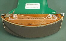

Ultrasonic transducers and ultrasonic sensors are devices that generate or sense ultrasound energy. They can be divided into three broad categories: transmitters, receivers and transceivers. Transmitters convert electrical signals into ultrasound, receivers convert ultrasound into electrical signals, and transceivers can both transmit and receive ultrasound.
Applications and performance
Ultrasound can be used for measuring wind speed and direction (anemometer), tank or channel fluid level, and speed through air or water. For measuring speed or direction, a device uses multiple detectors and calculates the speed from the relative distances to particulates in the air or water. To measure tank or channel liquid level, and also sea level (tide gauge), the sensor measures the distance (ranging) to the surface of the fluid. Further applications include: humidifiers, sonar, medical ultrasonography, burglar alarms and non-destructive testing.
Systems typically use a transducer that generates sound waves in the ultrasonic range, above 20 kHz, by turning electrical energy into sound, then upon receiving the echo turn the sound waves into electrical energy which can be measured and displayed.
This technology, as well, can detect approaching objects and track their positions.
Ultrasound can also be used to make point-to-point distance measurements by transmitting and receiving discrete bursts of ultrasound between transducers. This technique is known as Sonomicrometry where the transit-time of the ultrasound signal is measured electronically (ie digitally) and converted mathematically to the distance between transducers assuming the speed of sound of the medium between the transducers is known. This method can be very precise in terms of temporal and spatial resolution because the time-of-flight measurement can be derived from tracking the same incident (received) waveform either by reference level or zero crossing. This enables the measurement resolution to far exceed the wavelength of the sound frequency generated by the transducers.
Transducers


Ultrasonic transducers convert alternating current (AC) into ultrasound and vice versa. The transducers typically use piezoelectric transducers or capacitive transducers to generate or receive ultrasound. Piezoelectric crystals are able to change their sizes and shapes in response to voltage being applied. On the other hand, capacitive transducers use electrostatic fields between a conductive diaphragm and a backing plate.
The beam pattern of a transducer can be determined by the active transducer area and shape, the ultrasound wavelength, and the sound velocity of the propagation medium. The diagrams show the sound fields of an unfocused and a focusing ultrasonic transducer in water, plainly at differing energy levels.
Since piezoelectric materials generate a voltage when force is applied to them, they can also work as ultrasonic detectors. Some systems use separate transmitters and receivers, while others combine both functions into a single piezoelectric transceiver.
Ultrasound transmitters can also use non-piezoelectric principles such as magnetostriction. Materials with this property change size slightly when exposed to a magnetic field and make practical transducers.
A capacitor ("condenser") microphone has a thin diaphragm that responds to ultrasound waves. Changes in the electric field between the diaphragm and a closely spaced backing plate convert sound signals to electric currents, which can be amplified.
The diaphragm (or membrane) principle is also used in the relatively new micro-machined ultrasonic transducers (MUTs). These devices are fabricated using silicon micro-machining technology (MEMS technology), which is particularly useful for the fabrication of transducer arrays. The vibration of the diaphragm may be measured or induced electronically using the capacitance between the diaphragm and a closely spaced backing plate (CMUT), or by adding a thin layer of piezo-electric material on the diaphragm (PMUT). Alternatively, recent research showed that the vibration of the diaphragm may be measured by a tiny optical ring resonator integrated inside the diaphragm (OMUS).
Ultrasonic transducers can also be used for acoustic levitation.
Use in depth sounding

It involves transmitting acoustic waves into water and recording the time interval between emission and return of a pulse; the resulting time of flight, along with knowledge of the speed of sound in water, allows determining the distance between sonar and target. This information is then typically used for navigation purposes or in order to obtain depths for charting purposes. Distance is measured by multiplying half the time from the signal's outgoing pulse to its return by the speed of sound in the water, which is approximately 1.5 kilometres per second For precise applications of echosounding, such as hydrography, the speed of sound must also be measured typically by deploying a sound velocity probe into the water. Echo sounding is effectively a special purpose application of sonar used to locate the bottom. Since a traditional pre-SI unit of water depth was the fathom, an instrument used for determining water depth is sometimes called a fathometer. The first practical fathometer was invented by Herbert Grove Dorsey and patented in 1928.
Use in medicine

Medical ultrasonic transducers (probes) come in a variety of different shapes and sizes for use in making cross-sectional images of various parts of the body. The transducer may be used in contact with the skin, as in fetal ultrasound imaging, or inserted into a body opening such as the rectum or vagina. Clinicians who perform ultrasound-guided procedures often use a probe positioning system to hold the ultrasonic transducer.
Compared to other medical imaging modalities, ultrasound has several advantages. It provides images in real-time, is portable, and can consequently be brought to the bedside. It is substantially lower in cost than other imaging strategies and does not use harmful ionizing radiation. Drawbacks include various limits on its field of view, the need for patient cooperation, dependence on patient physique, difficulty imaging structures obscured by bone, air or gases, and the necessity of a skilled operator, usually with professional training. Owing to these drawbacks, novel wearable ultrasound implementations are gaining popularity. These miniature devices continuously monitor vitals and alert at the emergence of early signs of abnormality.
Use in industry

 An ultrasonic parking sensor (circular) mounted on a vehicle bumper
 Vehicle infotainment screen showing obstacles detected by the sensor
Ultrasonic sensors can detect the movement of targets and measure the distance to them in many automated factories and process plants. Sensors can have an on or off digital output for detecting the movement of objects, or an analog output proportional to distance. They can sense the edge of the material as part of a web guiding system.
Ultrasonic sensors are widely used in cars as parking sensors to aid the driver in reversing into parking spaces. They are being tested for a number of other automotive uses including ultrasonic people detection and assisting in autonomous UAV navigation.
Because ultrasonic sensors use sound rather than light for detection, they work in applications where photoelectric sensors may not. Ultrasonics is a great solution for clear object detection and for liquid level measurement, applications that photoelectrics struggle with because of target translucence. As well, target color or reflectivity do not affect ultrasonic sensors, which can operate reliably in high-glare environments.
Passive ultrasonic sensors may be used to detect high-pressure gas or liquid leaks, or other hazardous conditions that generate ultrasonic sound. In these devices, ultrasound from the transducer (microphone) is converted down to the human hearing range (Audible Sound = 20 Hz to 20 kHz).
High-power ultrasonic emitters are used in commercially available ultrasonic cleaning devices. An ultrasonic transducer is affixed to a stainless steel pan which is filled with a solvent (frequently water or isopropanol). An electrical square wave feeds the transducer, creating sound in the solvent strong enough to cause cavitation.
Ultrasonic technology has been used for multiple cleaning purposes. One of which that been gaining a decent amount of traction in the past decade is ultrasonic gun cleaning.
In ultrasonic welding and ultrasonic wire bonding, plastics and metals are joining using vibrations created by power ultrasonic transducers.
Ultrasonic testing is also widely used in metallurgy and engineering to evaluate corrosion, welds, and material defects using different types of scans.
Notes
- It is for this reason that the person subjected to ultrasound of organs that can contain quantities of air or gas, such as the stomach, intestine and bladder, must follow a food preparation designed to reduce their quantity: specific diet and supplements for the intestine and intake of non-carbonated water to fill the bladder; sometimes, during the examination, it may be required to fill the stomach with non-carbonated water.
References
- ^ Brook, Karen (2020-07-22). "Ultrasound Transducer Care and Handling Tips". Ultrasound. Retrieved 2022-02-20.
- Carotenuto, Riccardo; Merenda, Massimo; Iero, Demetrio; Della Corte, Francesco G. (July 2019). "An Indoor Ultrasonic System for Autonomous 3-D Positioning". IEEE Transactions on Instrumentation and Measurement. 68 (7): 2507–2518. Bibcode:2019ITIM...68.2507C. doi:10.1109/TIM.2018.2866358. S2CID 116511976.
- ^ Curry, TS; Dowdey, JE; Murry, RC (1990). Christensen's Physics of Diagnostic Radiology. Lippincott Williams & Wilkins. pp. 328–329. ISBN 978-0-8121-1310-5. Retrieved 2 February 2023.
- Salim, Muhammed Sabri; Abd Malek, M.F.; Heng, R.B.W.; Juni, K.M.; Sabri, Naseer (March 2012). "Capacitive Micromachined Ultrasonic Transducers: Technology and Application". Journal of Medical Ultrasound. 20 (1): 8–31. doi:10.1016/j.jmu.2012.02.001. S2CID 55610382.
- Westerveld, Wouter J (2014). Silicon photonic micro-ring resonators to sense strain and ultrasound (Ph.D.). Delft University of Technology. doi:10.4233/uuid:22ccedfa-545a-4a34-bd03-64a40ede90ac. ISBN 978-94-6259-079-3.
- S.M. Leinders; W.J. Westerveld; J. Pozo; P.L.M.J. van Neer; B. Snyder; P. O'Brien; H.P. Urbach; N. de Jong; M.D. Verweij (2015). "A sensitive optical micro-machined ultrasound sensor (OMUS) based on a silicon photonic ring resonator on an acoustical membrane". Scientific Reports. 5: 14328. Bibcode:2015NatSR...514328L. doi:10.1038/srep14328. PMC 4585719. PMID 26392386.
- Vieira, Silvio L.; Andrade, Marco A.B. (2020). "Translational and rotational resonance frequencies of a disk in a single-axis acoustic levitator". Дщд. 127 (22): 224901. Bibcode:2020JAP...127v4901V. doi:10.1063/5.0007149. S2CID 225744617.
- "Echo Sounding / Early Sound Methods". National Oceanic & Atmospheric Administration (NOAA). NOAA Central Library. 2006.
In answer to the need for a more accurate depth registering device, Dr. Herbert Grove Dorsey, who later joined the C&GS, devised a visual indicating device for measuring relatively short time intervals and by which shoal and deep depths could be registered. In 1925, the C&GS obtained the very first Fathometer, designed and built by the Submarine Signal Company.
- SCHNEIDER, MICHEL (1999). "Characteristics of SonoVue™". Echocardiography. 16 (s1). Wiley: 743–746. doi:10.1111/j.1540-8175.1999.tb00144.x. ISSN 0742-2822. PMID 11175217. S2CID 73314302.
- Srivastav, A.; Bhogi, K.; Mandal, S.; Sharad, M. (Aug 2019). "An Adaptive Low-Complexity Abnormality Detection Scheme for Wearable Ultrasonography". IEEE Transactions on Circuits and Systems. 66 (8): 1466–1470. doi:10.1109/TCSII.2018.2881612. S2CID 117391787.
- "Wearable Ultrasounds Poised to Revolutionize Healing and Pain Management Healthcare Market" (Press release). Jun 2021.
Further reading
- Escolà, Alexandre; Planas, Santiago; Rosell, Joan Ramon; Pomar, Jesús; Camp, Ferran; Solanelles, Francesc; Gracia, Felip; Llorens, Jordi; Gil, Emilio (2011-02-28). "Performance of an Ultrasonic Ranging Sensor in Apple Tree Canopies". Sensors. 11 (3): 2459–2477. doi:10.3390/s110302459. ISSN 1424-8220. PMC 3231637. PMID 22163749.