 Top of 7 litre steel cylinder with parallel neck thread with valve fitted Top of 7 litre steel cylinder with parallel neck thread with valve fitted | |
| Other names | Pillar valve |
|---|---|
| Uses | Controlling gas supply to scuba equipment |
A scuba cylinder valve or pillar valve is a high pressure manually operated screw-down shut off valve fitted to the neck of a scuba cylinder to control breathing gas flow to and from the pressure vessel and to provide a connection with the scuba regulator or filling whip. Cylinder valves are usually machined from brass and finished with a protective and decorative layer of chrome plating. A metal or plastic dip tube or valve snorkel screwed into the bottom of the valve extends into the cylinder to reduce the risk of liquid or particulate contaminants in the cylinder getting into the gas passages when the cylinder is inverted, and blocking or jamming the regulator.
Cylinder valves are classified by four basic aspects: the thread specification for attachment to the cylinder, the connection to the regulator, pressure rating, and some functional distinguishing features. Standards relating to the specifications and manufacture of cylinder valves include ISO 10297 and CGA V-9 Standard for Gas Cylinder Valves.
Structure of the valve

The valve body is usually machined from a solid brass casting or forging, which is screwed into the cylinder neck thread, and sealed by o-ring or thread tape. The outlet is machined to fit one of the standard scuba regulator connection systems, and a gas passage is provided from the interior of the cylinder to the regulator connection. Control of gas flow through the gas passage is by opening and closing a valve orifice machined into the valve body, by turning the valve knob to drive the valve spindle which moves the valve seat towards or away from the orifice. The spindle engages with the valve seat by a flat and slot or a square socket on the inner end of the spindle, which passes through the spindle seal in the valve bonnet. Rotation of the seat drives it along its axis on a screw thread concentric with the orifice. The spindle is usually sealed by an O-ring where it passes through the bonnet, and axial loads on the spindle are usually carried by a teflon or similar low friction coefficient washer. Other arrangements have been used, but the one described is very common and is known as a balanced valve because the pressure of the gas in the cylinder is exerted on both sides of the valve seat when it is not sealed, because the gas can leak past the threads of the seat. Historically, two other spindle arrangements were also used, the unbalanced valve where the periphery of the seat is sealed, and the glandless valve, where the valve seat does not rotate, but is sealed into the valve body behind a diaphragm. The valve outlet is connected to a regulator for diving, or a filling whip for charging. The valve must be open for these operations, and closed to keep the gas inside the cylinder for storage.
Cylinder neck threads
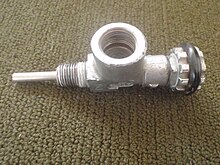
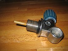

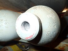

The neck of the cylinder is the part of the end which is shaped as a narrow concentric cylinder, and internally threaded to fit a cylinder valve. Cylinder threads may be in two basic configurations: Taper thread and parallel thread. The valve thread specification must exactly match the neck thread specification of the cylinder. Improperly matched neck threads can fail under pressure which can have fatal consequences. Parallel threads are more tolerant of repeated removal and refitting of the valve for inspection and testing.
There are several standards for neck threads, these include:
- Taper thread (17E), with a 12% taper right hand thread, standard Whitworth 55° form with a pitch of 14 threads per inch (5.5 threads per cm) and pitch diameter at the top thread of the cylinder of 18.036 millimetres (0.71 in). These connections are sealed using thread tape and torqued to between 120 and 150 newton-metres (89 and 111 lbf⋅ft) on steel cylinders, and between 75 and 140 N⋅m (55 and 103 lbf⋅ft) on aluminium cylinders.
Parallel threads are made to several standards:
- M25x2 ISO parallel thread, which is sealed by an O-ring and torqued to 100 to 130 N⋅m (74 to 96 lbf⋅ft) on steel, and 95 to 130 N⋅m (70 to 96 lbf⋅ft) on aluminium cylinders;
- M18x1.5 parallel thread, which is sealed by an O-ring, and torqued to 100 to 130 N⋅m (74 to 96 lbf⋅ft) on steel cylinders, and 85 to 100 N⋅m (63 to 74 lbf⋅ft) on aluminium cylinders;
- 3/4"x14 BSP parallel thread, which has a 55° Whitworth thread form, a pitch diameter of 25.279 millimetres (0.9952 in) and a pitch of 14 threads per inch (1.814 mm);
- 3/4"x14 NGS (NPSM) parallel thread, sealed by an O-ring, torqued to 40 to 50 N⋅m (30 to 37 lbf⋅ft) on aluminium cylinders, which has a 60° thread form, a pitch diameter of 0.9820 to 0.9873 in (24.94 to 25.08 mm), and a pitch of 14 threads per inch (1.814 mm);
- 3/4"x16 UNF, sealed by an O-ring, torqued to 40 to 50 N⋅m (30 to 37 lbf⋅ft) on aluminium cylinders.
- 7/8"x14 UNF, sealed by an O-ring.
The 3/4"NGS and 3/4"BSP are very similar, having the same pitch and a pitch diameter that only differs by about 0.2 mm (0.008 in), but they are not compatible, as the thread forms are different.
All parallel thread valves are sealed using an O-ring at the top of the neck thread which seals in a chamfer or step in the cylinder neck and against the flange of the valve.
Connection to the regulator

A rubber O-ring forms a seal between the metal of the cylinder valve and the metal of the diving regulator. Fluoroelastomer (e.g. viton) O-rings may be used with cylinders filled with oxygen-rich breathing gas mixtures to reduce the risk of fire. There are two basic types of cylinder valve to regulator connection in general use for scuba cylinders. They are both very widely used for cylinders containing air and in many countries also for other breathing gases for diving:
Yoke connectors
See also: Mechanism of diving regulators § CGA 850 connection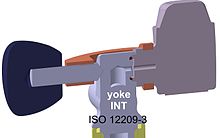
The yoke connector, also known as an A-clamp or international connector, is a component of the regulator that fits around the valve body at the outlet and presses the outlet O-ring of the valve against the inlet seat of the regulator. The connection is officially described as connection CGA 850 yoke. The yoke clamping screw is screwed down snug by hand to ensure metal to metal contact between the valve and regulator to sufficiently constrain the O-ring against extrusion. Overtightening can make the yoke impossible to remove later without tools. The seal is created by clamping the O-ring mounted in a groove on the face of the valve between the surfaces of the regulator and valve. When the valve is opened, cylinder pressure expands the O-ring against the outer surface of the O-ring groove in the valve and the face of the regulator inlet. This type of connection is simple, cheap and very widely used worldwide. Several O-ring sizes are in use, and both overall and section diameters may vary, but the correct size for the valve is necessary for a reliable seal and so that the O-ring does not easily fall out during handling and storage. It has a maximum pressure rating of 240 bar, and is not well protected against overpressurisation. Insufficient clamping force may allow the pressure to slightly stretch the yoke structure, opening a gap between the sealing faces of the valve and the regulator sufficient to extrude the O-ring through the gap, resulting in a potentially catastrophic leak. A similar effect can occur if the first stage is bumped against the environment, flexing the yoke enough to open a gap. When underwater this is most likely in an overhead environment where the diver cannot make an immediate emergency ascent. The risk of this cause for O-ring extrusion is roughly proportional to the pressure in the cylinder, and is less for a more rigid yoke structure. Older regulators may have a yoke rated at 200 bar, and these may not fit over more recent 240 bar valves.
DIN connectors
See also: Mechanism of diving regulators § DIN connection
In the DIN screw thread connectors, the regulator screws into the cylinder valve, trapping the O-ring securely between the sealing face of the valve and the O-ring groove in the regulator. These are more reliable than A-clamps because the O-ring is well protected and the assembly is considerably more rigid, and has a lower profile, making O-ring extrusion under impact less likely, but operators in many countries do not widely use DIN filling connectors on compressors, or cylinder valves which have DIN fittings, so a diver traveling abroad with a DIN system may need to take an adaptor, either for connecting the DIN regulator to a rented cylinder, or for connecting an A-clamp filler hose to a DIN cylinder valve. The DIN connection is slightly more complex to manufacture, but if the seal is good when the valve is opened it is likely to remain good throughout a dive, even if banged against a solid overhead, and is consequently preferred by technical divers even where the yoke fitting is more generally popular. DIN connections are available in two specifications; for working pressures up to 232 bar, and for 300 bar. The original design 200 bar regulator fitting with five threads will not seal in a 300 bar valve, preventing potential overload, particularly of the high pressure hose and submersible pressure gauge, but the DIN 300 bar regulator inlet fitting with seven threads available on almost all recent regulators is compatible with 200 and 232 bar valves as well as the 300 bar valves. The thread form is G5/8" x 14 tpi. The O-ring is carried in a groove on the regulator. Two sizes of O-ring are in common use.
Adaptors
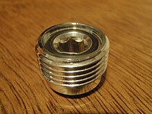


Adaptors are available to allow connection of DIN regulators to yoke cylinder valves (A-clamp or yoke adaptor), and to connect yoke regulators to DIN cylinder valves. There are two types of adaptors for DIN valves: plug adaptors and block adaptors. Plug adaptors are screwed into a 5-thread DIN valve socket, are rated for 232/240 bar, and can only be used with valves which are designed to accept them. These can be recognised by a dimple recess opposite to the outlet opening, used to locate the screw of an A-clamp. Block adaptors are generally rated for 200 bar, and can be used with almost any 200 bar 5-thread DIN valve. A-clamp or yoke adaptors comprise a yoke clamp with a DIN socket in line. They are slightly more vulnerable to O-ring extrusion than integral yoke clamps, due to greater leverage on the first stage regulator.
Conversion kits
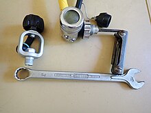
Several manufacturers market an otherwise identical first stage varying only in the choice of cylinder valve connection. In these cases it may be possible to buy original components to convert yoke to DIN and vice versa. The complexity of the conversion may vary, and parts are not usually interchangeable between manufacturers. The conversion of Apeks regulators is particularly simple and only requires an Allen key and a ring spanner.
Valves for gases other than air
There are also cylinder valves for scuba cylinders containing gases other than air:
- The European Norm EN 144-3:2003 introduced a new type of valve, similar to existing 232 bar or 300 bar DIN valves, but with a metric M26×2 thread connecting the cylinder to the regulator. These are intended to be used for breathing gas with oxygen content above that normally found in natural atmospheric air (i.e. 22–100%). From August 2008, these were required in the European Union for all diving equipment used with nitrox or pure oxygen. The idea behind this new standard is to prevent a rich mixture being filled to a cylinder that is not oxygen clean. However even with use of the new system there still remains nothing except human procedural care to ensure that a cylinder with a new valve remains oxygen-clean - which is exactly how the previous system worked. The enriched oxygen valve may alert the user to a non-air breathing gas, but will give no indication of the actual composition of the contents. Filling adaptors are available as a stock item to allow filling of cylinders fitted with these valves from a standard G5/8" DIN filling connector.
- An M 24x2 male thread cylinder valve was supplied with some Dräger semi-closed circuit recreational rebreathers (Dräger Ray) for use with nitrox mixtures. The regulator supplied with the rebreather had a compatible connection.
Internal and other replaceable components of valves are often interchangeable amongst other valves from the same manufacturer for similar service.
Handwheel
The handwheel or valve knob is a knurled or ridged rubber, plastic or metal fitting attached to the valve spindle, used to rotate the spindle to open and close the valve. Hard rubber or tough plastic are the usual materials on recent models, usually incorporating moulded grips and a metal insert to engage the square or flatted part of the spindle, to which they are usually attached by a slotted nut.
Dip tube
The dip tube, anti-debris tube, or valve snorkel is a short tube screwed into the hole in the bottom of the valve body, which projects into the cylinder internal space. Its function is to prevent any loose debris inside the cylinder from getting into the outlet passages if the cylinder is inverted in use, as such material may clog or jam the regulator. Originally mostly made from brass tube, they are also often made from plastic, but brass is still preferred for high oxygen fraction gas mixes, as it is a lower fire hazard. Some dip tubes have a filter attached to the lower end, often made from sintered brass, but most have a plain opening.
Pressure rating
Yoke valves are rated between 200 and 240 bar, and there does not appear to be any mechanical design detail preventing connection between any yoke fittings, though some older yoke clamps will not fit over the popular 232/240 bar combination DIN/yoke cylinder valve as the yoke is too narrow.
DIN valves are produced in 200 bar and 300 bar pressure ratings. The number of threads and the detail configuration of the connections is designed to prevent incompatible combinations of filler attachment or regulator attachment with the cylinder valve.
- 232 bar DIN (5-thread, G5/8) Outlet/Connector #13 to DIN 477 part 1 - (technically they are specified for cylinders with 300 bar test pressure)
- 300 bar DIN (7-thread, G5/8) Outlet/Connector #56 to DIN 477 part 5 - these are similar to 5-thread DIN fitting but are rated to 300 bar working pressures. (technically they are specified for cylinders with 450 bar test pressure). The 300 bar pressures are common in European diving and in US cave diving.
Other distinguishing features
Plain valves

The most commonly used cylinder valve type is the single outlet plain valve, sometimes known as a "K-valve", which allows connection of a single regulator, and has no reserve function. It simply opens to allow gas flow, or closes to shut it off. Several configurations are used, with options of DIN or A-clamp connection, and vertical or transverse spindle arrangements.
Reserve valves


Until the 1970s, when submersible pressure gauges on regulators came into common use, diving cylinders often used a mechanical reserve mechanism to indicate to the diver that the cylinder was nearly empty. The gas supply was automatically cut-off by a spring loaded valve when the gas pressure reached the reserve pressure. To release the reserve, the diver pulled down on a rod that ran along the side of the cylinder and which activated a lever to open a bypass valve. The diver would then finish the dive before the reserve was consumed. The reserve could be adjusted by spring stiffness, typically 300 pounds per square inch (21 bar)for a single cylinder, but for twin sets 500 pounds per square inch (34 bar) and triple sets 700 pounds per square inch (48 bar). On occasion, divers would inadvertently trigger the mechanism while donning gear or performing a movement underwater and, not realizing that the reserve had already been accessed, could find themselves out of air at depth with no warning whatsoever. These valves became known as "J-valves" from being item "J" in one of the first scuba equipment manufacturer catalogs. The standard non-reserve yoke valve at the time was item "K", and is often still referred to as a "K-valve". J-valves are still occasionally used by professional divers in zero visibility, where the submersible pressure gauge (SPG) can not be read. While the recreational diving industry has largely discontinued support and sales of the J-valve, the US Department of Defense, the US Navy, NOAA (the National Oceanographic and Atmospheric Administration) and OSHA (the national Occupational Health and Safety Administration) all still allow or recommend the use of J-valves as an alternative to a bailout cylinder or as an alternative to a submersible pressure gauge. They are generally not available through recreational dive shops, but are still available from some manufacturers. They can be significantly more expensive than K-valves from the same manufacturer.
Less common in the 1950s to 1970s was an "R-valve" which was equipped with a restriction that caused breathing to become difficult as the cylinder neared exhaustion, but that would allow less restricted breathing if the diver began to ascend and the ambient water pressure lessened, providing a larger pressure differential over the orifice. It was never particularly popular because if it was necessary for the diver to descend during exit from a cave or wreck, breathing would become progressively more difficult as the diver went deeper, eventually becoming impossible until the diver could ascend to a low enough ambient pressure.
The reserve valves manufactured by Dräger were similar in function to the spring loaded J-valve, but the reserve valve completely bypassed the main valve when opened. Poseidon at one stage marketed a manifold for twin cylinders which featured a pair of plain valves in the cylinders, with a reserve valve mounted on the central outlet block of the manifold. This mechanism retained reserve pressure in both cylinders, where the usual arrangement with manifolded cylinders was to have the reserve gas retained in only one cylinder, therefore necessitating the use of different springs to maintain a roughly constant proportion of the total gas supply.
When filling the cylinder the J-valve will obstruct the inward flow of gas unless both the main and reserve valves are opened.
-
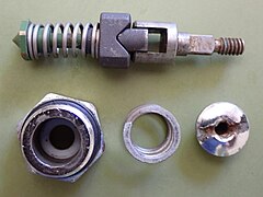 Sherwood J-valve components of the reserve mechanism
-
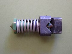 Reserve seat mechanism open position
-
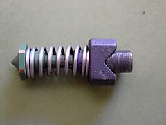 Reserve seat mechanism closed position
Dual outlet valves

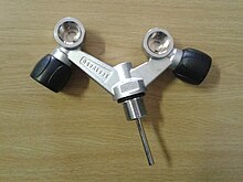

Y and H cylinder valves have two outlets, each with its own valve, allowing two regulators to be connected to the cylinder. If one regulator "freeflows", which is a common failure mode, or ices up, which can happen in water below about 5 °C, its valve can be closed and the cylinder breathed from the regulator connected to the other valve. The difference between an H-valve and a Y-valve is that the Y-valve body splits into two posts roughly 90° to each other and 45° from the vertical axis, looking like a Y, while an H-valve is usually assembled from a valve designed as part of a manifold system with an additional valve post connected to the manifold socket, with the valve posts parallel and vertical, which looks a bit like an H. Y-valves are also known as "slingshot valves" due to their appearance. Another style of dual outlet valve has the openings at 90° to each other and to the cylinder centreline. These are used on rebreather cylinders so that a bailout regulator can be fitted as well as the rebreather supply regulator.
Handed valves
Some cylinder valve models have axial spindles - in line with the cylinder axis, and are not handed. Standard side-spindle valves have the valve knob on the diver's right side when back-mounted. Side-spindle valves used with manifolds must be a handed pair - one with the knob to the right and the other with the knob to the left, but in all cases the valve is opened by turning the knob anticlockwise, and closed by turning it clockwise. This is the convention with almost all valves for all purposes. Left and right hand side-spindle valves are used by sidemount divers. These may be blanked off manifold valves or specially made for the purpose.
Modular valves
Valves which can be assembled as single or dual outlet valves, or as the paired valves of a manifold system are known as modular valves. They are generally available as left and right hand valves, with a second unvalved outlet into which a blanking plug, a second valve, or the end of a plain or isolation manifold can be screwed. The secondary outlet for one side may have left hand thread, usually indicated by a groove around the hexagon of the nut, as manifolds usually have some centre distance adjustment by rotating the manifold on its axis, which will screw it into or out of both valves at the same time. This makes it necessary to have matching thread on the plugs or secondary valves.
A more complex modular valve system was introduced by Poseidon, where a wide variety of configurations could be assembled out of a set of standardised parts.
Bursting disk
See also: Diving cylinder § Safety
Some national standards require that the cylinder valve includes a bursting disk, a pressure relief device that will release the gas before the cylinder fails in the event of overpressurization. If a bursting disk ruptures during a dive the entire contents of the cylinder will be lost in a very short time. The risk of this happening to a correctly rated disc, in good condition, on a correctly filled cylinder is very low. Burst disk over-pressure protection is specified in the CGA Standard S1.1. Standard for Pressure Relief Devices. Bursting disc rupture pressure is generally rated at 85% to 100% of test pressure.
Accessories
Additional components for convenience, protection or other functions, not directly required for the function as a valve.
Manifolds
Main article: Scuba manifold
A cylinder manifold is a tube which connects two cylinders together so that the contents of both can be supplied to one or more regulators. There are three commonly used configurations of manifold. The oldest type is a tube with a connector on each end which is attached to the cylinder valve outlet, and an outlet connection in the middle, to which the regulator is attached. A variation on this pattern includes a reserve valve at the outlet connector. The cylinders are isolated from the manifold when closed, and the manifold can be attached or disconnected while the cylinders are pressurised.
More recently, manifolds have become available which connect the cylinders on the cylinder side of the valve, leaving the outlet connection of the cylinder valve available for connection of a regulator. This means that the connection cannot be made or broken while the cylinders are pressurised, as there is no valve to isolate the manifold from the interior of the cylinder. This apparent inconvenience allows a regulator to be connected to each cylinder, and isolated from the internal pressure independently, which allows a malfunctioning regulator on one cylinder to be isolated while still allowing the regulator on the other cylinder access to all the gas in both cylinders. These manifolds may be plain or may include an isolation valve in the manifold, which allows the contents of the cylinders to be isolated from each other. This allows the contents of one cylinder to be isolated and secured for the diver if a leak at the cylinder neck thread, manifold connection, or burst disk on the other cylinder causes its contents to be lost. A relatively uncommon manifold system is a connection which screws directly into the neck threads of both cylinders, and has a single valve to release gas to a connector for a regulator. These manifolds can include a reserve valve, either in the main valve or at one cylinder. This system is mainly of historical interest.
Valve cage
Also known as a manifold cage or regulator cage, this is a structure which can be clamped to the neck of the cylinder or manifolded cylinders to protect the valves and regulator first stages from impact and abrasion damage while in use and from rolling the valve closed by friction of the handwheel against an overhead. A valve cage is often made of stainless steel, and some designs can snag on obstructions and lines.
Dust caps

Plastic covers are held over the opening by friction, or screwed into a DIN valve socket to keep dust and spray from entering the opening. They are generally not 100% reliable, and it is considered prudent to open the valve slightly to blow out any contamination before making a connection to filler hose or regulator.
Extension handle
A valve knob extension (slob knob) is a fairly long flexible extension to a valve spindle allowing the diver to open and close the valve if it is in a position where the diver cannot normally reach it.
Standards
Standards relating to the specifications and manufacture of cylinder valves include ISO 10297 and CGA V-9 Standard for Gas Cylinder Valves, both of which specify design, testing and marking of cylinder valves to be fitted as a closure to refillable transportable gas cylinders. The 8th edition of CGA V-9 brings it into alignment with ISO 10297.
References
- ^ NOAA Diving Program (U.S.) (28 February 2001). "Section 5.7 Compressed gas cylinders". In Joiner, James T (ed.). NOAA Diving Manual, Diving for Science and Technology (4th ed.). Silver Spring, Maryland: National Oceanic and Atmospheric Administration, Office of Oceanic and Atmospheric Research, National Undersea Research Program. ISBN 978-0-941332-70-5. CD-ROM prepared and distributed by the National Technical Information Service (NTIS)in partnership with NOAA and Best Publishing Company
- Staff (2016). "Advanced Open Water Diver Course - Standard Scuba Tank Features". Rancho Santa Margarita, California: PADI. Retrieved 16 January 2016.
- ^ Harlow, Vance (1999). Scuba regulator maintenance and repair. Warner, New Hampshire: Airspeed press. ISBN 0-9678873-0-5.
- ^ Barsky, Steven; Neuman, Tom (2003). Investigating Recreational and Commercial Diving Accidents. Santa Barbara, California: Hammerhead Press. ISBN 0-9674305-3-4.
- ^ "High pressure cylinder valves" (PDF). Cavagna group, Ponte S. Marco di Calcinato, Italy. Retrieved 9 February 2018.
- ^ Roberts, Fred M. (1963). Basic Scuba: Self contained underwater breathing apparatus: Its operation, maintenance and use (2nd ed.). New York: Van Nostrand Reinholdt.
- "Diver injury during air cylinder recharging". International Marine Contractors Association. 18 December 2014. Retrieved 28 July 2010. M25x2 valve, cylinder had a Whitworth imperial thread of 1 inch (25.4 mm)
- "Injuries due to failure of diver's emergency gas cylinder". International Marine Contractors Association. 18 December 2014. Retrieved 25 January 2019. M25x2 valve in 3/4"x14tpi cylinder
- "Injuries due to failure of divers emergency gas cylinder – use of incompatible threads". International Marine Contractors Association. 7 January 2016. Retrieved 25 January 2019. M25x2 cylinder, 3/4″x14 BSP valve
- Transcript of the court records of Inquest No. 96/2015. Cape Town: Magistrates court for the district of the Cape. 30 November 2015.
- ^ Barker, Jim (14 June 2002). Luxfer gas cylinders: Questions and answers from the technical seminars held in South Asia, Jan/Feb 2002 (Report). Luxfer Asia-Pacific.
- Technical Committee 58 Gas cylinders (25 March 1999). ISO 11116-1: Gas cylinders - 17E taper thread for connection of valves to gas cylinders (First ed.). Geneva, Switzerland: International Standards Organization.
- ^ Technical Committee ISO/TC 58, Gas cylinders (15 October 1997). ISO 13341:1997 Transportable gas cylinders - Fitting of valves to gas cylinders (1st ed.). Geneva, Switzerland: International Standards Organisation.
- Committee MCE/18 (1986). Specification for pipe threads for tubes and fittings where pressure-tight joints are not made on the threads (metric dimensions). British Standard 2779 (Technical report). London: British Standards Institution. ISBN 0-580-15212-X.
- Metal Cutting Tool Institute (1989). "Tap and Die section: American Standard Gas Cylinder Valve Threads". Metal Cutting Tool Handbook (illustrated ed.). Industrial Press Inc. p. 447. ISBN 978-0-8311-1177-9. Retrieved 7 December 2016.
- ^ Staff. "Valving of SCUBA (Air) Cylinders". Support documents. Garden Grove, California: Catalina Cylinders. Retrieved 13 November 2016.
- Staff. "Luxfer Limited 106". Catalog. XS Scuba. Retrieved 7 August 2016.
- ^ Harlow, Vance (2001). Oxygen Hacker's Companion (4th ed.). Warner, New Hampshire: Airspeed Press.
- Compressed Gas Association (1990). Handbook of Compressed Gases (3rd ed.). New York City: Chapman and Hall. p. 229. ISBN 978-1-4612-8020-0. Retrieved 17 January 2016.
- Staff. "Valves and Neck Threads - Regulator Fittings and SCUBA Valves". Pompano Beach, Florida: Dive Gear Express, LLC. Retrieved 16 January 2016.
- ^ Staff. "San-o-Sub DIN/K Cylinder Valve - 232 bar". Melbourne, Victoria: The Scuba Doctor. Retrieved 6 January 2016.
- ^ Staff. "How to select a SCUBA tank". www.divegearexpress.com. Pompano Beach, Florida: Dive Gear Express, LLC. Archived from the original on 15 April 2015. Retrieved 8 November 2016.
- "Valves & Manifolds". www.diveavenue.com. DiveStock. Retrieved 27 January 2021.
- Staff (August 1999). "DrägerRay Mixed Gas-Rebreather Instructions for Use" (PDF). 90 21 365 - GA 2215.000 de/en (2nd ed.). Lübeck, Germany: Dräger Sicherheitstechnik GmbH. pp. 46–88. Retrieved 8 November 2016.
- NOAA Diving Program (U.S.) (December 1979). "4: Diving equipment". In Miller, James W. (ed.). NOAA Diving Manual, Diving for Science and Technology (2nd ed.). Silver Spring, Maryland: US Department of Commerce: National Oceanic and Atmospheric Administration, Office of Ocean Engineering. pp. 4–9.
- ^ US Navy (2006). "Section 7-2.2 Open circuit scuba". US Navy Diving Manual, 6th revision. Washington, D.C.: US Naval Sea Systems Command. Retrieved 15 September 2016.
- Stone, W.C. (1986). Mitchell, C.T. (ed.). Design of fully redundant autonomous life support systems. Diving for Science 86. Proceedings of the American Academy of Underwater Sciences Sixth Annual Scientific Diving Symposium. (Report). Dauphin Island, Alabama: American Academy of Underwater Sciences.
- Dowding, Scott (2003). The Recreational Diver's Dictionary & Historical Timeline. Bloomington, Indiana: iUniverse. ISBN 978-0-595-29468-8.
- Staff. "12L Concave Euro Cylinder with Left or Right Hand Valve". DirDirect Worldwide product catalog. Portland, UK: Underwater Explorers Ltd. Retrieved 16 January 2016.
- "Apeks Left and Right hand Cylinder Valve". Products. Blackburn, United Kingdom: Apeks Marine Equipment. Archived from the original on 8 November 2016. Retrieved 16 January 2016.
- "Valves". www.divegearexpress.com. Dive Gear Express. Retrieved 27 January 2021.
- "DGX Premium Modular Valve, Right (Typical Side)". www.divegearexpress.com. Dive Gear Express. Retrieved 27 January 2021.
- "Modular scuba mono valve AIR DIN 232 bars M25x2". www.diveavenue.com. Dive Avenue. Retrieved 27 January 2021.
- ^ Gilliam, Bret C; Von Maier, Robert; Crea, John (1992). Deep diving: an advanced guide to physiology, procedures and systems. San Diego, California: Watersport Publishing, Inc. ISBN 0-922769-30-3. Retrieved 10 January 2016.
- ISO 10297:2014 Gas cylinders — Cylinder valves — Specification and type testing (Limited preview). International Standards Organization. Retrieved 22 January 2021 – via Svenska institutet för standarder.
- "CGA's V-9 Publication Defines Key Factors for Compressed Gas Cylinder Valve Safety". www.cganet.com. Compressed Gas Assiociation. 5 November 2020. Retrieved 25 January 2021.